Hardware Flow Control
For hardware flow control, the UART module utilizes a RTS/CTS flow control scheme commonly found in RS-232 (Recommended Standard 232) networks. The RS-232 standard defines the signals connecting Data Terminal Equipment (DTE) to Data Communication Equipment (DCE). In addition to the standard transmit (TX) and receive (RX) lines, RTS flow control uses the Request-to-Send (RTS) and Clear-to-Send (CTS) lines. The UART module also provides a third line, the Transmit Drive Enable (TXDE) line, to control an RS-485 transceiver.
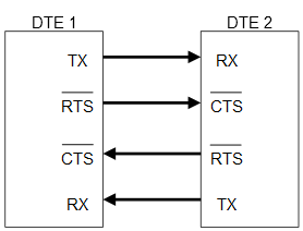
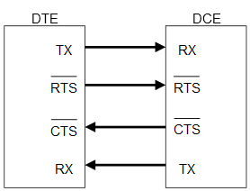
The UART module is configured as a DTE device; therefore, UART hardware configures the RTS signal as an output, while the CTS signal is an input. In a DCE system, the opposite is true; the RTS signal is an input, while the CTS signal is an output. It is important to note that connections between DTE and DTE devices (Figure 1) are different than connections between DTE and DCE devices (Figure 2).
The active-low RTS and CTS signals work together to control transmission flow. Hardware flow is typically controlled by the DTE device, which could be considered a ‘master’ device. In the case of a DTE-to-DTE configuration, either device can act as a master. When one DTE device wishes to transmit data, the DTE device pulls the RTS line low, which signals the slave device, through its CTS input, to begin to monitor its RX input. When the slave device is ready to accept the data, it pulls its RTS line low, informing the master, through its CTS line, to begin sending data. Once the transaction has completed, the master device pulls the RTS line high.
In a DTE-to-DCE configuration, the DTE is considered the master and the DCE is considered a slave. In this configuration, when the DTE device wishes to transmit data, the DTE device pulls the RTS line low, which signals the DCE device, through its RTS line, to begin to monitor its RX line. When the DCE device is ready to accept the data, it pulls its CTS line low, informing the DTE device, through its CTS connection, to begin sending data.


No comments:
Post a Comment